INOX hydrostations for clean water

INOX hydrostations for clean water

Description

Hydrostations are intended to maintain pressure in the sanitary or hydrant water supply network of high-rise buildings, hotels, hospitals and schools in residential areas, residential buildings, or industrial facilities. They are also intended for water pumping in various industries.

The pressure in the city network is usually too low to supply high-rise buildings with water. Appropriate pressure and enough water for the sanitary or hydrant network are provided by a hydrostation placed in the basement of the building. Hydropower stations are designed as compact devices with two or three vertical pumps controlled by a microprocessor. Versions with frequency control of pump speeds ensure a constant pressure in the plumbing. The hydrostation can be installed in a relatively small space and does not require additional installations in the building. This means that it can replace an old dilapidated hydrophore device.

Technical characteristics

Flow: from 10 to 350 l/min

Lifting pumping height: up to 170m

Motor power: 0.75 ÷ 7.5 kW

Power supply: 3-phase (400V)

Medium temperature: from 0°C to + 130°C

Ambient temperature: from 0°C to + 40°C

Weight: 25 – 112kg

The hydrostation is designed as a compact whole. The pumps are equipped with three-phase direct-start electric motors. Thermocouples are installed in the windings of electric motors to protect against overload.

All components are mounted on a joint base which allows easy transport and easy installation. The installation of the hydrostation is carried out by installing it in a room that is separated from the living quarters by appropriate insulation, in order to prevent the transmission of noise. Although the hydrostation is equipped with rubber feet, we recommend placing the station on a base made of a material that prevents the transmission of vibrations. It should be placed in the room in a way that it is at least 1 m away from the wall on all sides. This will allow easy access during servicing. The pressure and suction connection of the station is possible from the left or from the right. The hydro station is connected to the local water supply network or draws water from the collection basin, in which the water level is above the hydrostation. In case the level in the reservoir is lower than the pump, we must use a special hydrostation, where each pump will have its own suction pipe to the reservoir. When starting the hydrostation, it is necessary to make an electrical connection in accordance with the operating instructions, set the operating parameters and check the pressure in the diaphragm pressure vessels.

On and off control is performed by a microprocessor that controls on and off by means of an analog pressure sensor on the pressure connection of the hydrostation. The setting can be arbitrary and can be done using the switch next to the LCD screen in the control box. Most often the setting of the same on and off pressures is chosen. In this way, we achieve the smallest pressure fluctuations at the pressure connection of the hydrostation.

Purpose of use

for drinking water management

supply of facilities to increase water inflow

domestic use for the care of single-family houses

for larger irrigation systems

industrial purposes

plumbing systems

Tall buildings (blocks, hospitals, hotels, schools, and various other institutions)

Utilities

Hydrant systems

Water pumping stations

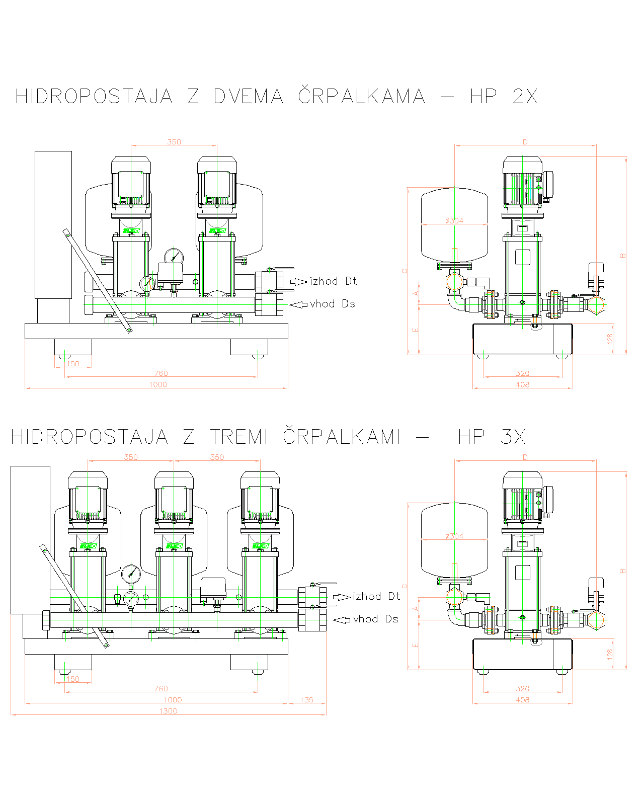
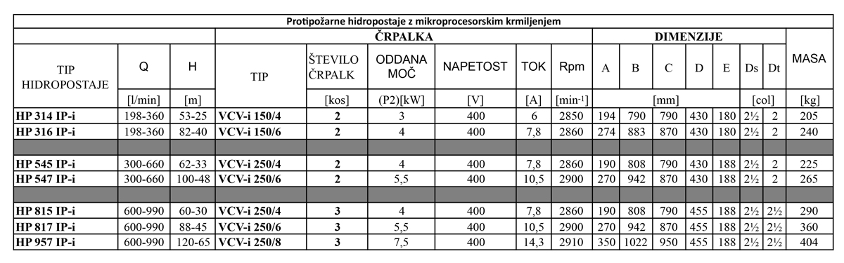
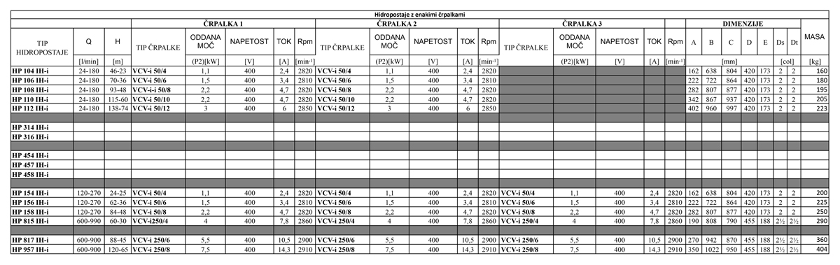
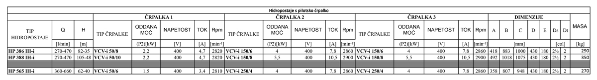
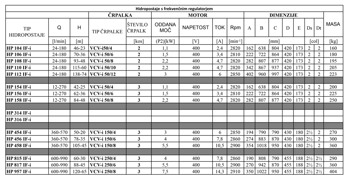
Depending on the purpose of using the hydrostation, we divide it into 3 basic types in which several different designs are then possible:

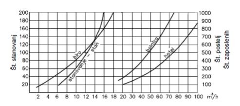
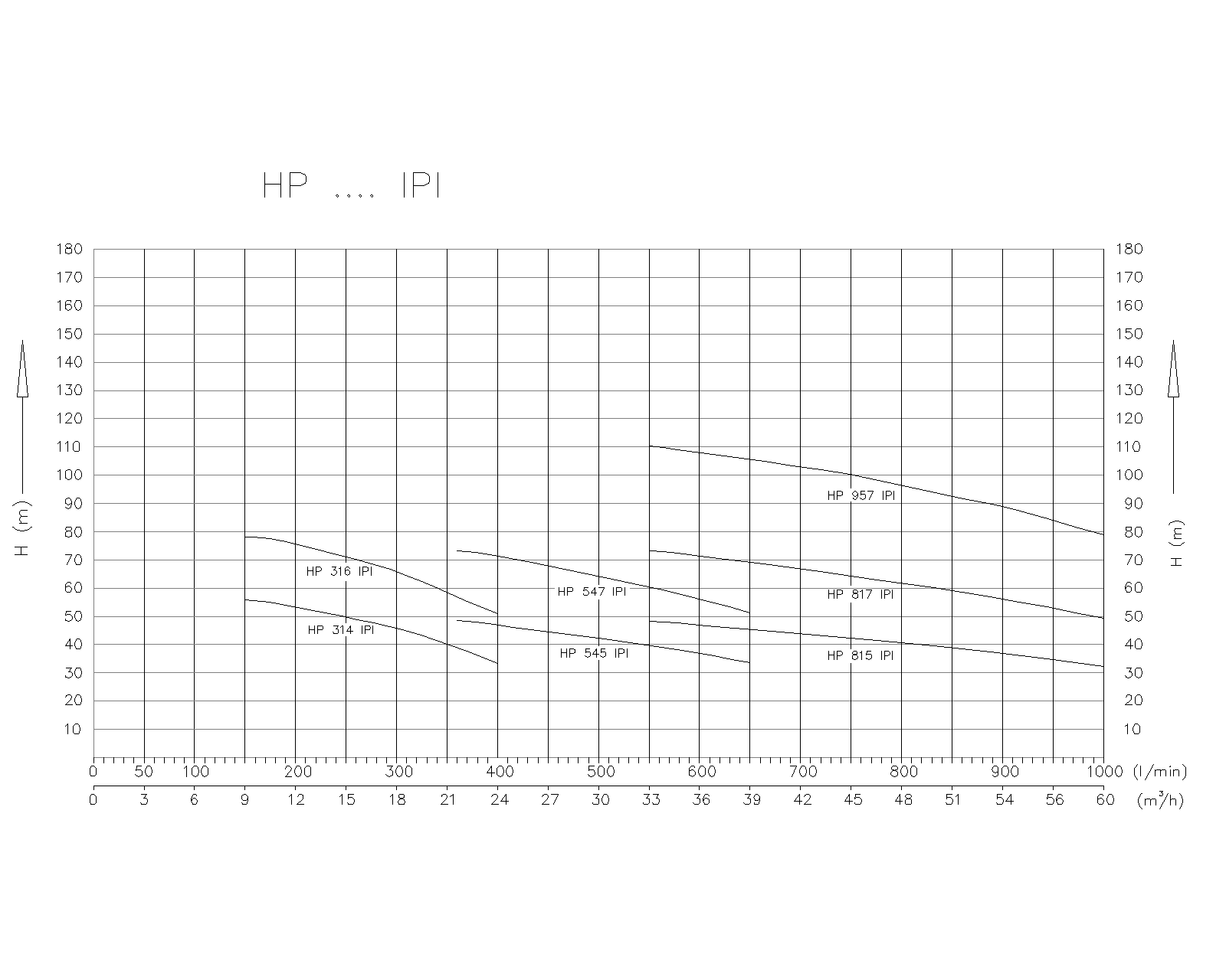
The correct choice of the hydrostation is made by a detailed calculation of the required flow and pressure and based on compliance with the applicable regulations for individual areas of operation. The recommendations from the diagram below can be used to facilitate and informatively estimate the required flow. When determining the flow for firefighting hydro stations, it is necessary to additionally take into account the prescribed flow on an individual hydrant (2.5 l/s) and the number of simultaneously operating hydrants. The required pressure of the hydrostation is the sum of:

pressure to overcome the height of the building,

pressure at the highest outlet,

pressure losses in the network.

When the station is directly connected to the local water supply, the value of the required pressure is reduced to the amount of pressure at the suction connection.

In the case of stations without frequency control, the switching pressure of the pumps is thus determined. The shut-off pressure of the pumps is 1 to 1.5 bar higher. The hydraulic station must be selected so that it reaches the pump shut-off pressure at reduced flow.

Required flow estimation diagram

Hydrostation components

1. vertical multistage pumps

2. control cabinet

3. non-return diaphragm valve at all pump pressure connections

4. common pressure pipe with:

pressure sensor

manometer

membrane pressure vessels

shut-off valve

5. common suction hose with:

pressure switch or the supplied float switch

shut-off valve

6. support

7. rubber feet included

8. supplied rubber expansion joints with flanges for pressure and suction connection of sanitary stations

Diagram

Hydrostation characteristics (Q/H Diagram)

Table

Submit an inquiry

Related products: