Three-phase asynchronous electric motors with short-circuit cage of closed design, with power up to 11 KW
Three-phase asynchronous electric motors with short-circuit cage of closed design, with power up to 11 KW
Description
Low Voltage Asynchronous Electric Motors “High Efficiency IE2 and IE3 Motors”
Data of three-phase asynchronous electric motors with short-circuit cage, protection degree IP 54, for power range from 0.06kW to 7.5kW (11kW) are described. Electric motors are built in accordance with the regulations of the International Electrotechnical Commission (IEC). The electric motors comply with IEC 60034, IEC 60072, IEC 60085, and DIN VDE 0530 T1 standards.
Use
Electric motors are suitable for the widest use in industry, crafts and agriculture.
Mechanical design
Protection level and cooling mode
Electric motors are built for IP 54 protection level according to IEC 60034-5. IP 54 protection prevents contact of live parts and contact of internal rotating parts. The electric motor is built in such a way that it does not allow the ingress of harmful dust and water, even when spraying water from all sides. When installing the electric motor outdoors, especially in a vertical position, we recommend an additional cover that protects the electric motor against the ingress of water along the shaft of the electric motor. Normal electric motors are built without holes for condensate drainage. In cases where condensation may occur due to climatic influences on the electric motor, condensate drain holes must be specifically requested when ordering. Cooling is performed by an external fan on the shaft of the electric motor and by an internal one which swirls the air by means of wings on the rotor of the electric motor (IEC 60034-6).
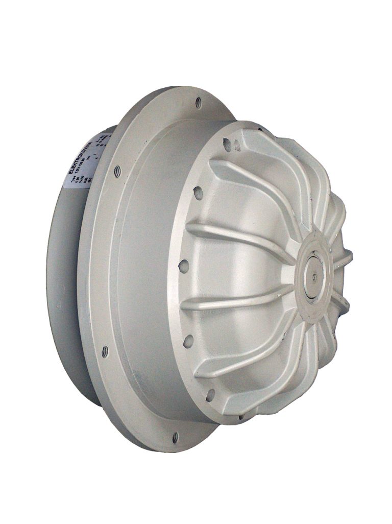
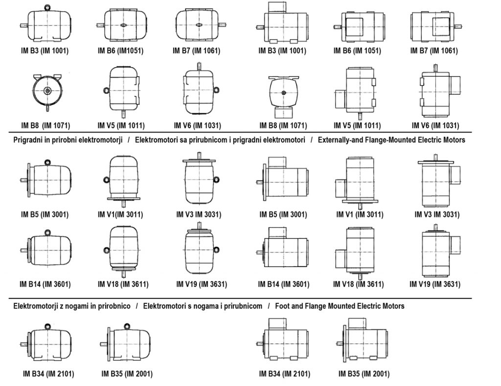
Shapes
The designations of the shapes of electric motors are defined by abbreviations according to IEC 60034-7. The basic forms are: IM B3, IM B5 and IM B14. From these forms it is possible to derive all the forms shown in the table. An IM B5 or IM B14 electric motor can be assembled from an IM B3 electric motor by reassembly (except 3T 80). In this case, it is necessary to unscrew the legs of the electric motor and replace the bearing shield of IM B3 shape with the shield of IM B5 or IM B14 shape and shorten the connecting screws. For the 2T series electric motors it is also necessary to seal the threaded holes for attaching the legs.
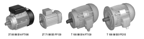
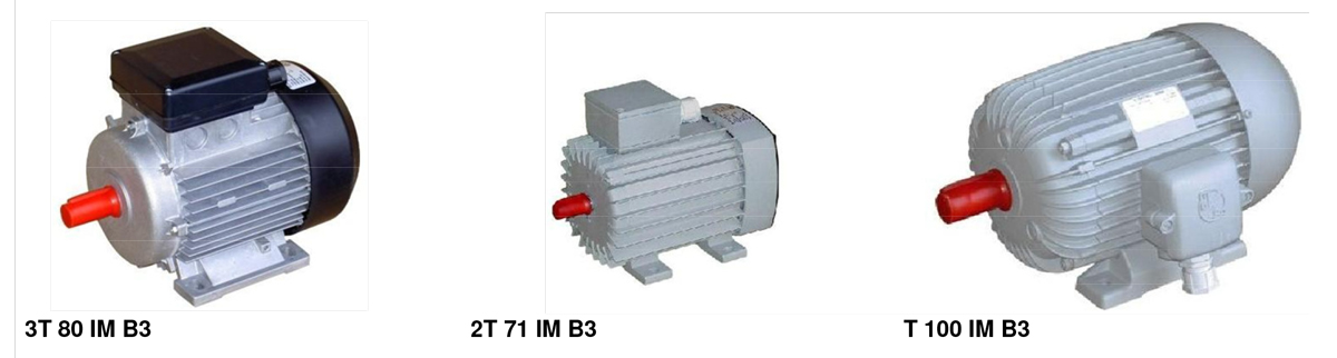
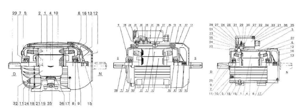
Shapes of electric motors T, 2T, 3T
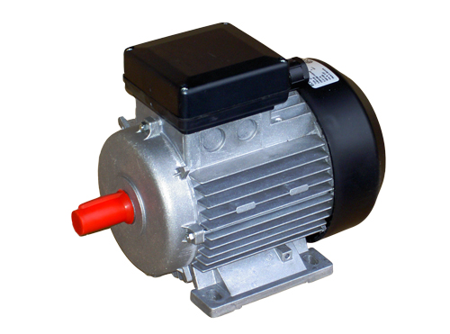
Electric motors with legs
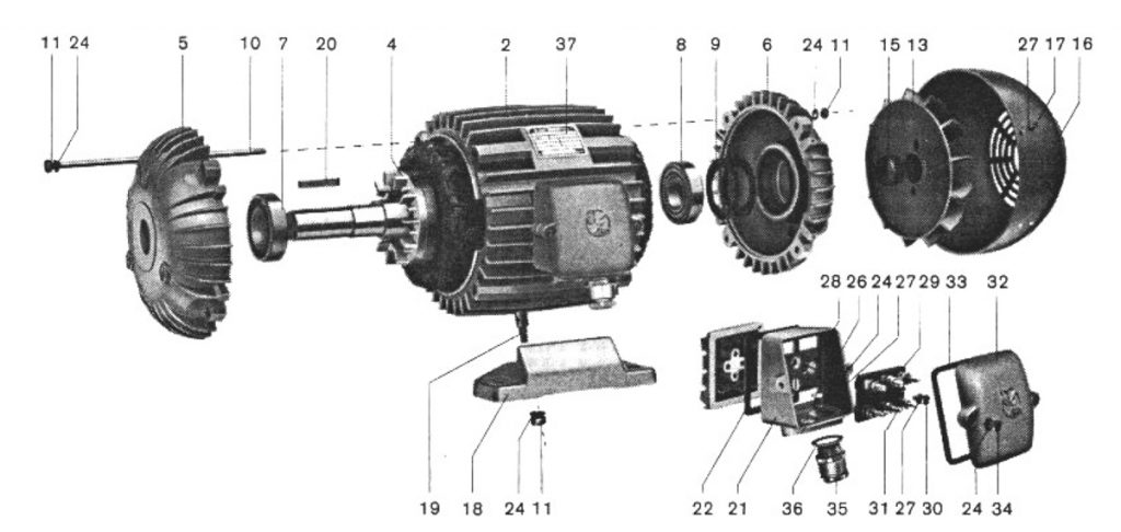
Electric motor, disassembled, Type T 100 IM B3
Electric motor, disassembled, Type 3T 80 IM B3
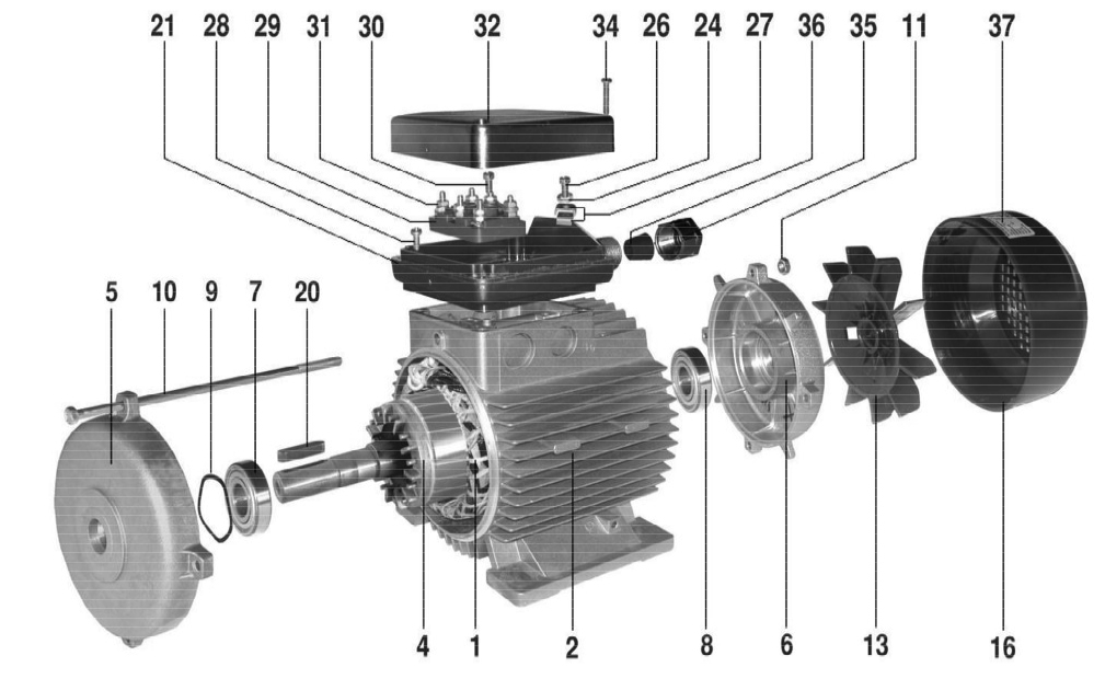
Electric motor, disassembled, Type 2T 71 IM B3
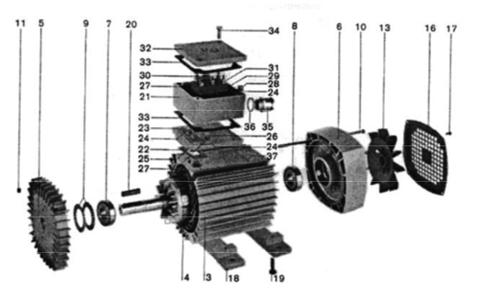
Design version T 100 IM B3, 3T 80 IM B3 and 2T 71 IM B3
Stator
Stator housing – cast
Stator housing – compressed profile
Rotor
Bearing shield, D
Bearing shield, N
Ball bearing, D
Ball bearing, N
Circular spring
10. Connecting screw
11. Coupling screw nut
12. Ventilation part
13. Fan
15. Tolerance ring
16. Fan cap
17. Screw
18. Foot
19. Leg screw
20. Dowel
21. Connection box
Cabinet base seal Cabinet base screw
Cabinet base screw
Base plate
Earthing screw
Washer
Cabinet screw
Connection plate
Connection plate screw
Screw for electrical connection with associated nuts, washers, and coupling
Cabinet cover
Cabinet cover gasket
Cover screw
Entry
Entry seal
Nominal data plate
D – Drive side of the engine
N – Side opposite the drive
Electrical version
Rated power
The powers given in the tables are the rated powers emitted by the electric motors on the shafts at constant load, at rated voltage and frequency, at an ambient temperature not exceeding 40°C and at an altitude of up to 1,000m.
Change of power
The power of the electric motor may decrease or increase if the following operating conditions are changed:
1. if the mains voltage or frequency changes by more than ± 6%
2. if the cooling conditions change
3. if electric motors are operated at a special drive
4. if the electric motors must comply with regulations other than Publ. IEC 60034-1, 60034-2 or DIN VDE 0531 T1.
Voltage and frequency
Standard electric motors are motors built for mains connection ∆230V/Y400V, 50Hz or ∆265V/Y460V, 60Hz for powers up to and including 3kW. Higher power motors are built for mains voltages ∆400V/50Hz and ∆460V/60Hz.
The permissible deviation from the rated voltage or frequency is ± 6%. By special order, we manufacture electric motors for voltages in the range from 110V to 600V and for the frequency of 50 and 60Hz. When the voltage and frequency change simultaneously in the same ratio, the electric motor does not need to be modified. Thus, an electric motor built for 400V/50Hz can be connected to the 460V/60Hz network. This will increase the speed by about 20% and increase the power by about 15%. However, we must take into account that under certain conditions the torque of the load changes with increasing speed.
Change in cooling conditions
The normal temperature of the ambient cooling air is up to 40°C. Deviation from this temperature causes the following power changes:
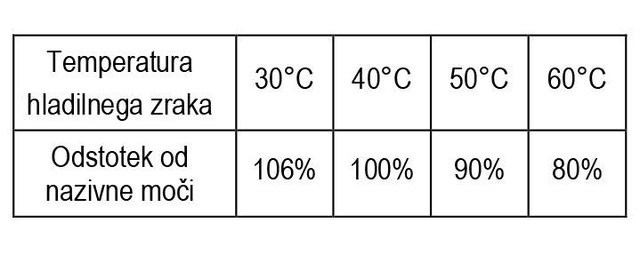
The electric motor can be loaded with a rated power when installed at an altitude higher than 1,000m, if the ambient air temperature for each additional 100m altitude is lower by about 0.8°C.
Insulation
The insulation of electric motors corresponds to insulation class F according to IEC Publ. 60034 or Publ. 60085 and DIN VDE 0530 T1. The heating of the windings of electric motors at rated powers in the tables corresponds to insulation class B. The insulation of the winding is tropical in the standard version and is suitable for both normal climatic conditions and very humid rooms.
Starting electric motors
Electric motors built for a voltage of ∆ 230V/Y 400V can only be started directly, and electric motors for a voltage of ∆ 400V can also be started with a star-delta switch. In this case, we have to take into account that the starting torque and the starting current in the star contact fall to about 1/3 of the values given in the tables.
Thermal protection of electric motors
Users of electric motors can protect the electric motors themselves by using circuit breakers. When choosing switches, they need to take into account the tolerances for voltage, frequency, efficiency (η) and power factor (cosj). The manufacturer’s instructions for these switches must be observed when selecting circuit breakers. At the request of our customers, we install automatic thermal protection switches (bimetals) or thermal sensors (thermistors) in the windings of electric motors, with which we can perform complete protection of electric motors. Automatic thermal protection switches for electric motors of lower power can be connected directly to the winding circuit, but for higher powers it is necessary to additionally connect contactors.
Electronic shut-off devices need to be additionally attached to the thermal sensors. The described types of protection work independently of external influences or types of drives because they react only to the temperature of the windings. With thermal sensors, the electric motor is completely protected against short circuits, overloads, and phase failures.
Automatic thermal protection switches are connected directly to the winding circuit for electric motors of lower power, and contactors must be additionally attached for higher power.
Electric motors for multiple rotational speeds
Electric motors for two speeds of rotation
Electric motors for three speeds of rotation
Electric motors with reduced (reduced) vibrations of stage R
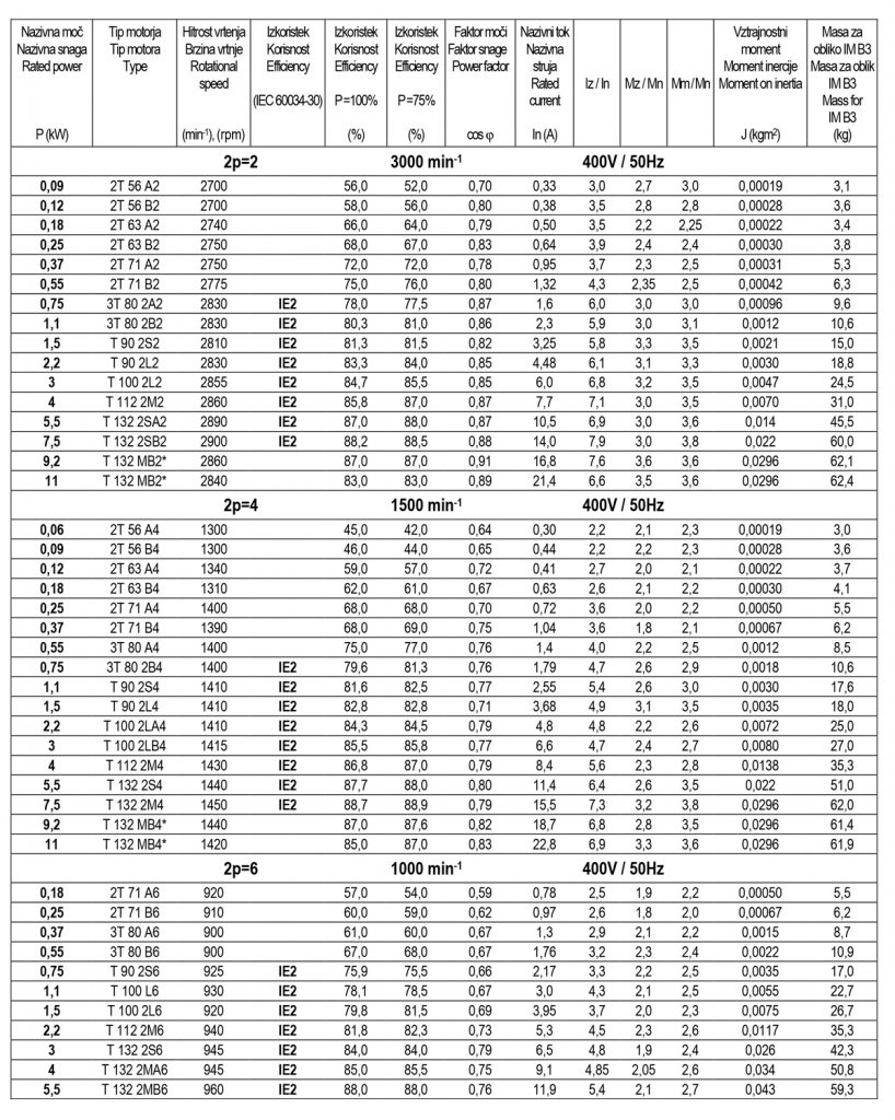
Operating data of three-phase asynchronous electric motors IE2
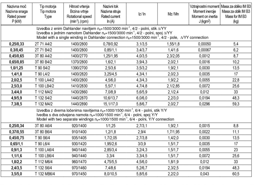
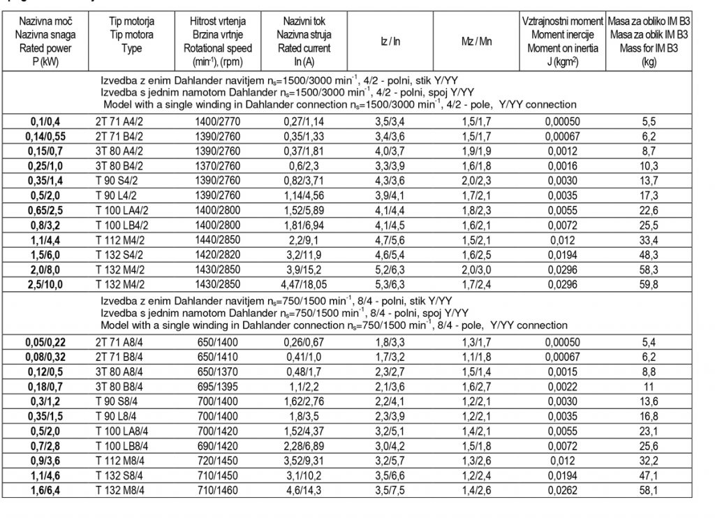
Operating data of three-phase asynchronous electric motors for two rotational speeds
Operating data of three-phase asynchronous electric motors for two speeds for fan drive
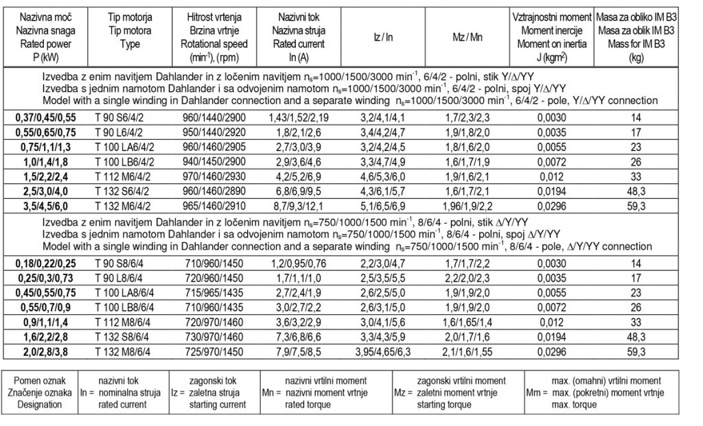
Operating data of three-phase asynchronous electric motors for three rotational speeds
Operating data of three-phase asynchronous electric motors for three rotational speeds
Normal voltage: 400V; frequency: 50Hz; protection level: IP 54; cooling mode: IC 411
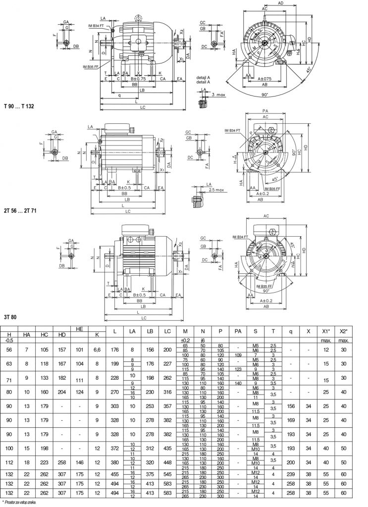
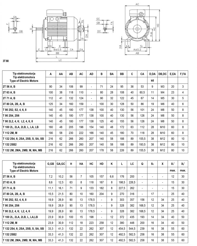
Dimensions of three-phase asynchronous electric motors
Shape with legs: IM B3 (IM B6, IM B7, IM B8, M V5, IM V6)
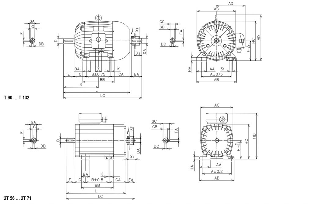
Dimensions of three-phase asynchronous electric motors
Attachment form: IM B14 (IM V18, IM V19)
Folder format: IM B5 (IM V1, IM V3)
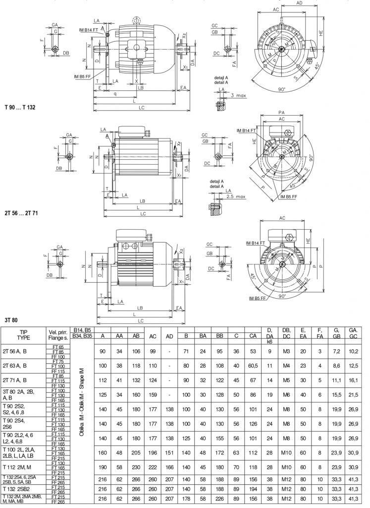
Dimensions of three-phase asynchronous electric motors
Attachment form with feet: IM B34
Flange form with feet: IM B35