Pusher
Pusher
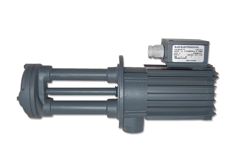
Description
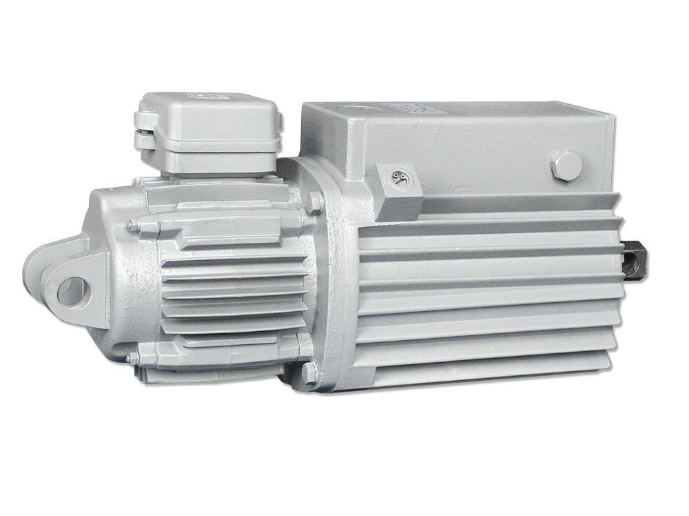
Pushers are hydrodynamic mechanisms designed for installation on the brakes of elevators or other devices that can operate even in particularly demanding conditions. Such conditions are usually found in metallurgical plants, where there is a lot of dust in the atmosphere, and due to the proximity of foundry furnaces a high ambient temperature is possible. The pushers act on the brakes as openers, i.e. they overcome the braking force and spread the brake calipers with the force of the lifting rod. Pushers with built-in springs also work in the opposite direction. The spring force acts on the brake mechanism as a brake force.
Technical characteristics
Length of movement: from 50 to 120 mm
Lifting force: from 125 to 2000N
Engine power: 0.15 ÷ 0.65kW
Power supply: 3-phase (400V),
Medium temperature: from -20°C to + 40°C
Weight: 18 – 53kg
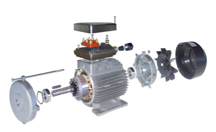
The electric motor is driven by a pump impeller which pumps hydraulic oil under the piston and lifts it. The piston transmits the force to the mechanism to which the rig is connected via the lifting rod. After switching off the electric motor, the oil pressure on the piston ceases and the latter returns to the initial position due to the influence of external forces or due to the force of the spring and squeezes the hydraulic oil into the space above the piston. Oil flows through the valve body. When valves are installed in this housing, the oil flow can be regulated, thus influencing the speed of raising and lowering the piston. The pump impeller is made with radial blades, so the operation of the pusher is independent of the direction of rotation of the electric motor. At the customer’s request, the device is equipped with a sensor that acts as a limit switch to indicate the position of the piston rod. The sensor detects the position of the piston and transmits an electrical signal to the terminal box.
A pusher consists of a three-phase electric motor and a centrifugal pump and parts of the transmission mechanism which are built into the housing of the pusher. The parts of the transmission mechanism are:
valve housing,
control valves,
piston,
lifting rod and
return springs.
Due to the reliability of operation, each pusher has two springs. Thus, when using brake pads, only part of the braking force is lost when one spring fails. The sealing of the electric motor shaft up to the size of EHT 50-50 is secured with a rubber seal, and in larger versions with a mechanical seal which also allows to increase the pressure in the housing due to the increase in oil temperature, which is especially important for operation at high ambient temperatures. The housing is designed to allow cooling of the hydraulic oil in it. The lifting rod, which is sealed with a rubber seal, is made of hardened stainless steel and is therefore wear-resistant. The housing of the machine and the electric motor is made of aluminum alloy, and the shield of the electric motor with the mounting lug is made of gray cast iron. The construction of the electric motor and the pusher is completely made in the way that it is protected from the intrusion of dust or splashing water into the interior. The protection of the terminal box is implemented in class IP 55.
Pushers can operate in all positions from vertical to horizontal, and the oil filler openings must always be on the upper side. This ensures that the space above the piston is filled with oil and that air is retained in a special chamber. The mechanism to which the pusher is attached should restrict the movement of the piston so that its movement is not fully utilized. This prevents the piston from hitting the pusher housing. The table shows the permissible frequency of switching on the electric motor, at which the electric motor does not overheat. The rated force of the pusher is the force on the lifting rod of the pusher without the built-in springs. In the case of a pusher with built-in springs, the force of the piston is used to compress the spring, and the force on the lifting rod is sufficient only to overcome the friction in the mechanism to which it is connected. After switching off the electric motor, a spring force acts on the lifting rod, which changes as the piston moves. The rated force appears at the point when the piston is raised by ⅓ of the entire stroke. Pushers can operate at ambient temperatures from -20°C to + 40°C. Pushers are built for connection to a 400V/50Hz network. By special order, pushers can be made for voltages in the range of 110V to 600V and for the frequencies of 50Hz and 60Hz.
Lifting and lowering time
The time of raising and lowering the piston is influenced by the load of the pusher or the force acting on the lifting rod. Time-travel diagrams show this interdependence in pushers without built-in springs and in open control valves. Due to the inertia of the rotor of the electric motor and the pump impeller, a certain delay occurs when lowering the piston. Rapid lowering of the piston can be achieved by condenser braking of the electric motor, which is especially important with the brakes on the load-lifting mechanism. The capacitors are connected in parallel between the phases of the drive electric motor, as shown in the diagram.
In the case of pushers with built-in valves, the time of raising and lowering the piston can also be extended as desired. By tightening the adjusting screws, we dampen the oil flow and thus influence the speed of the piston movement. This is important for pushers mounted on the brakes of load-carrying mechanisms, because soft braking is achieved by regulating the pushers. The regulation of raising and lowering the piston are mutually independent. Capacitors used for rapid descent:
EHT 12.5 – 50… .EHT 50 – 50, 10μF 400V
3EHT 80 – 60… .EHT 200 – 60, 16 μF 400V
Take care of regular maintenance and thus extend the service life
Before use, the pusher must be filled with a light, non-foaming hydraulic oil with a viscosity of less than 21 mm2/s at 50°C. During normal operation, it is necessary to change the oil once a year, but when the machine is operating at high ambient temperatures, it is necessary to change the oil several times. After one year of operation, we also recommend replacing the seal on the axis of the electric motor. The seal must be replaced before complete wear, as this is the only way to prevent oil from entering the electric motor. A detailed description of maintenance is attached in the operating instructions.
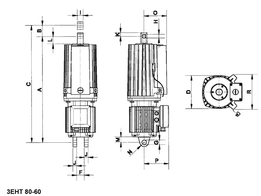
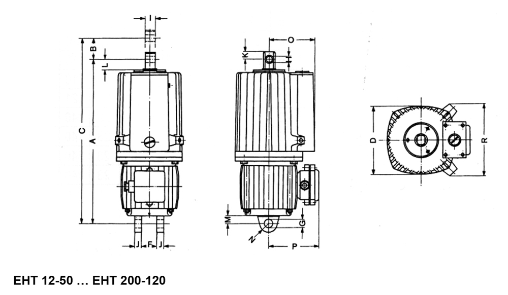
Basic technical data:
The correct choice and labeling of the pusher:
Marking of pushers
Pushers are marked by the strength of the lifting force and the length of the piston stroke. Pushers with built-in control valves are marked with an additional letter [V], pushers with built-in springs are marked with an additional letter [F], and pushers with an additional built-in piston position sensor are marked with an additional letter [S]. Examples of labeling the most common designs:
Pusher with lifting force 800 N, stroke 60 mm, without control valves and without springs: 3EHT 80-60.
Pusher with lifting force of 500 N, stroke 50 mm, with integrated control valves and without springs: EHT 50-50 V.
Pusher with lifting force of 1250 N, stroke 60 mm, without control valves and with built-in springs: EHT125-60 F.
Pusher with lifting force of 320 N, 50 mm stroke, with built-in control valves and with built-in springs: EHT 32-50 FV.
Pusher with lifting force of 800 N, stroke 60 mm, without control valves, without springs and with a 3EHT 80-60 S sensor.
Pusher with lifting force of 500 N, stroke 50 mm, with built-in control valves, without springs and with an EHT 50-50 VS sensor.
Pusher with lifting force of 1250 N, stroke 60 mm, without control valves, with built-in springs and with an EHT 125-60 FS sensor.
Pusher with lifting force of 320 N, stroke 50 mm, with built-in control valves, with built-in springs and with an EHT 32-50 FVS sensor.
Purpose of use
Lift brake systems
Industrial purposes
Farms
For home use
Construction
Foundries
Machines
Opening various heavy locks and machine doors
Table


Diagram